My Learjet 45 Home Cockpit (63 posts)
Landing at Alghero Fertilia LIEA, Online on IVAO
A short video about the landing at Alghero Fertilia LIEA airport, after taking off from Milan Malpensa LIMC, replicating the real flight we would have done a few days later.
Flight performed online on IVAO with ITOP13 callsign, also with the help of my new baby-copilot
MOBIFLIGHT - Input interface buttons
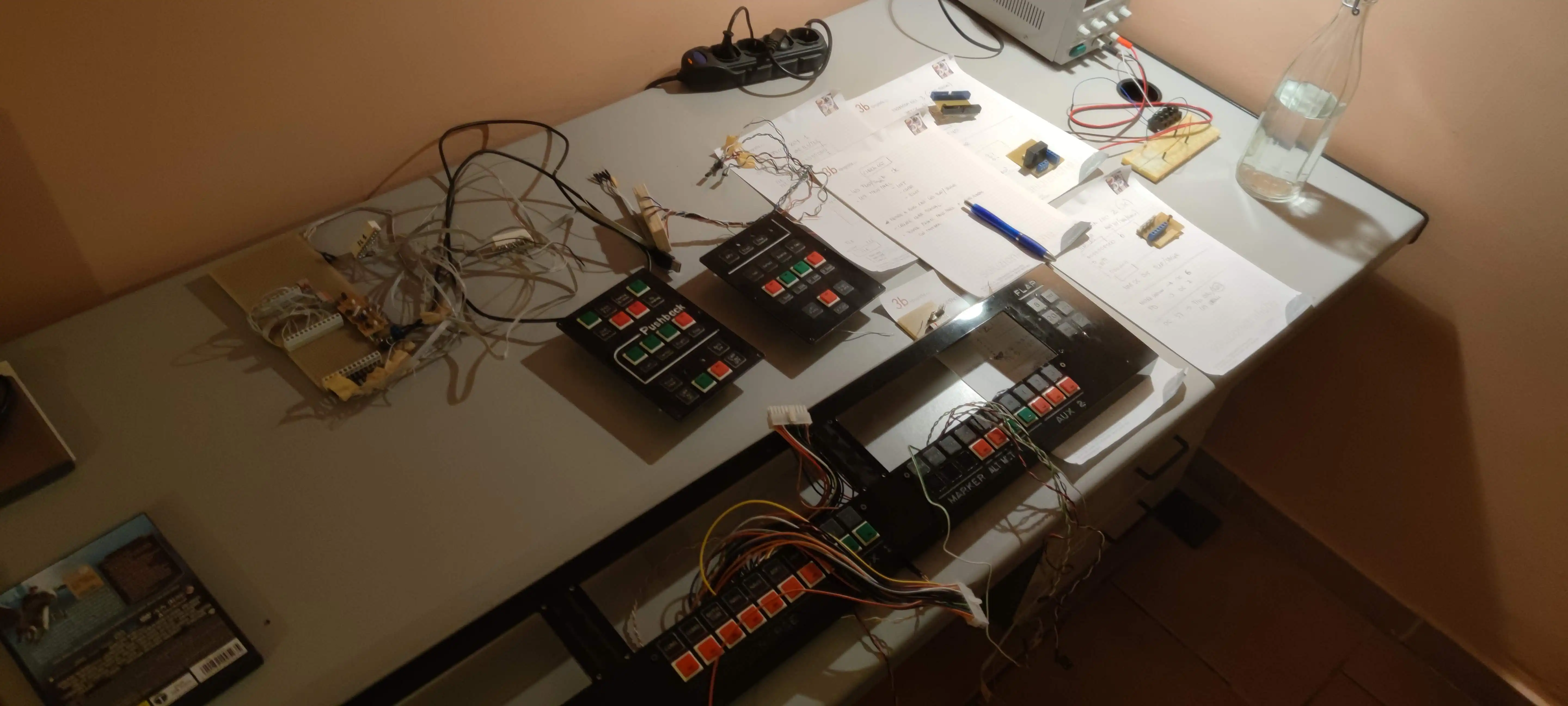
Obviously, a self-respecting simulator must try to make the "game" experience as realistic as possible. It is therefore essential to make most of the functions and actions available through real buttons, without using the keyboard or mouse.
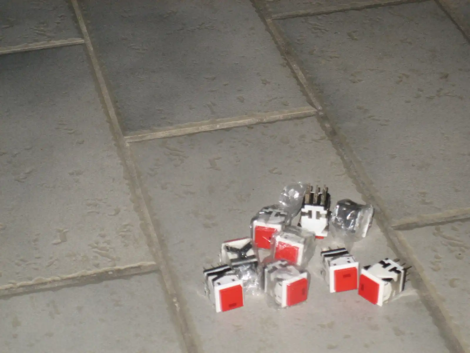
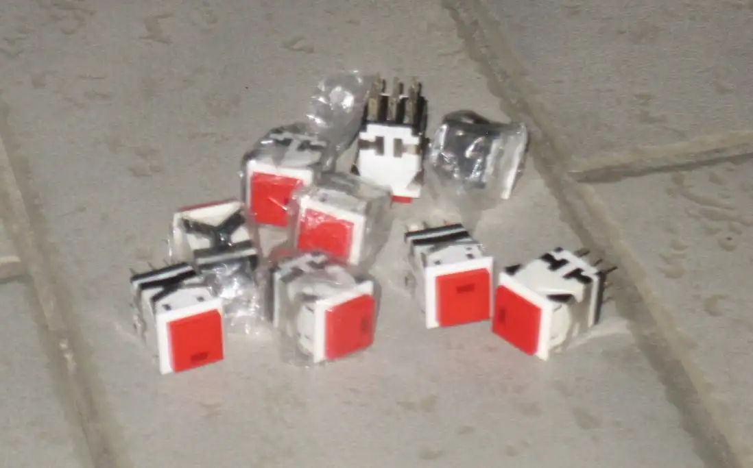
So I got physical buttons and switches to interface with the simulator to activate the features not implemented by the logitech (ex saitek) panels.
This particular model is convenient because it also has an integrated LED ... but today we are talking about INPUT and not OUTPUT, so I limit myself to the button.
Once you decide where to mount the buttons and what actions to assign, all you have to do is use a hardware interface to connect them to the simulator.
My first choice (perhaps the cheapest) was to emulate a keyboard and make each press of a button correspond to a press of a keyboard key; in this way it would have been sufficient to assign to that particular key the function attributed to the button (for this idea I was inspired by Dave Ault). The first version of my simulator used this method...with a keyboard I was able to map all the main buttons.
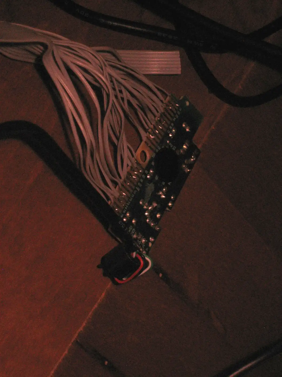
What is this method about? It is sufficient to recover the electronic circuit of a keyboard and with a lot of patience to solder some wires to its pins...By shorting two pins the pressure of a key is simulated. So, once we found the combinations of pins to short, it was sufficient to connect the contacts of the buttons and then map the button to an action of the simulator via FSUIPC. To make the connections I used a very simple flat cable (those used for IDE Hard Disks). The final result, in its * roughness *, was very functional and effective.
In this new version 2 of the simulator I abandoned this method because due to a connection error I literally burned the keyboard...
I then evolved towards more stable solutions and discovered the fantastic MOBIFLIGHT software, open source and free.
Through the use of two software modules it is possible, using compatible microcontrollers, to interface INPUT and OUTPUT to the simulator and configure them as deemed appropriate.
A software module is installed on the PC and allows system configurations; the second software module is a firmware to be installed on the microcontroller.
After doing some tests, I decided to adopt it as a definitive solution for INPUT management, using an ARDUINO NANO board as a microcontroller. All you had to do was connect the buttons to the ARDUINO pins, connect the ARDUINO via USB to your PC and configure the button bindings using the Windows software.
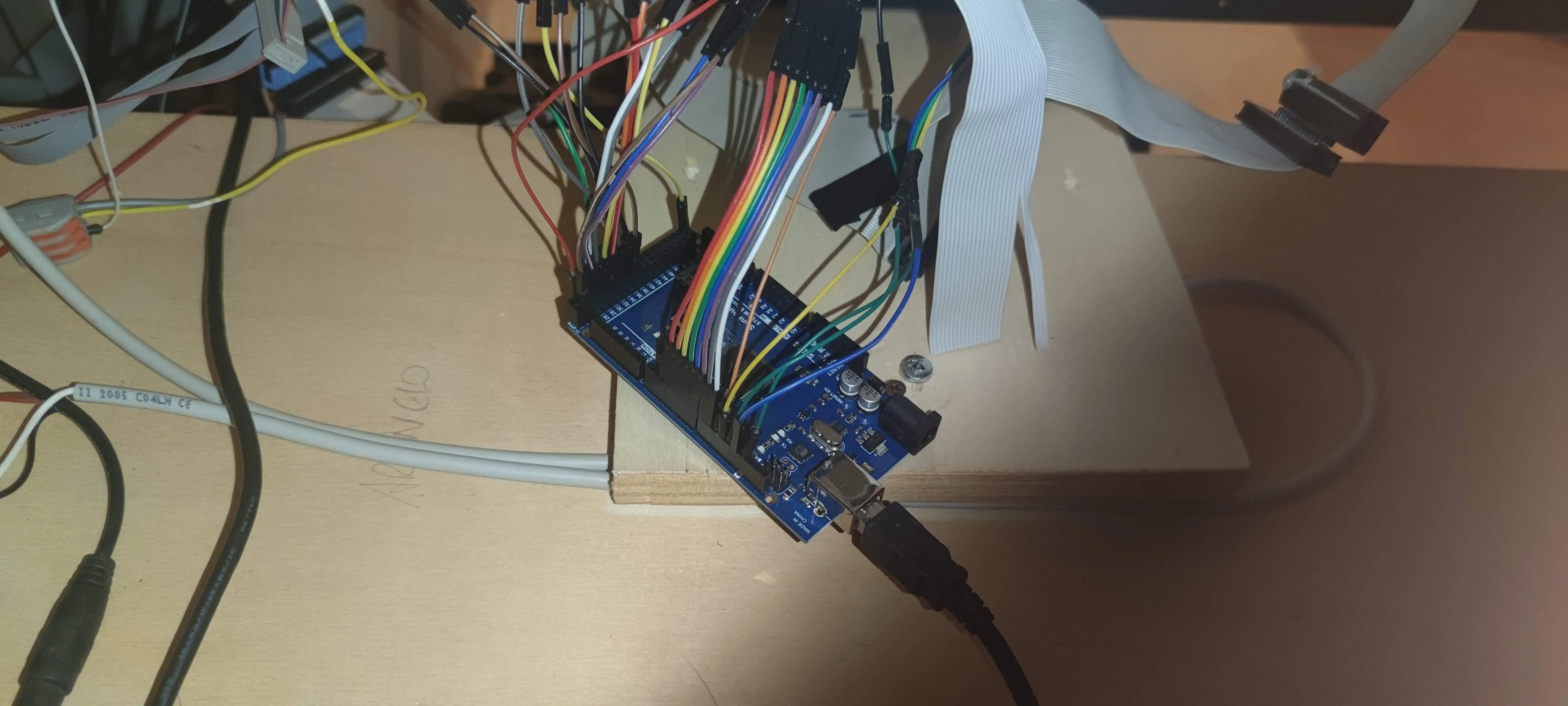
I leave you with a short video showing the tests done with MOBIFLIGHT and ARDUINO

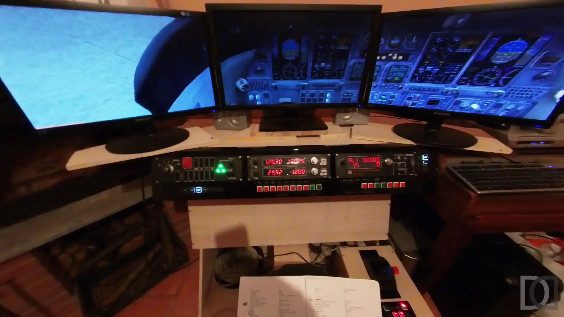
External views
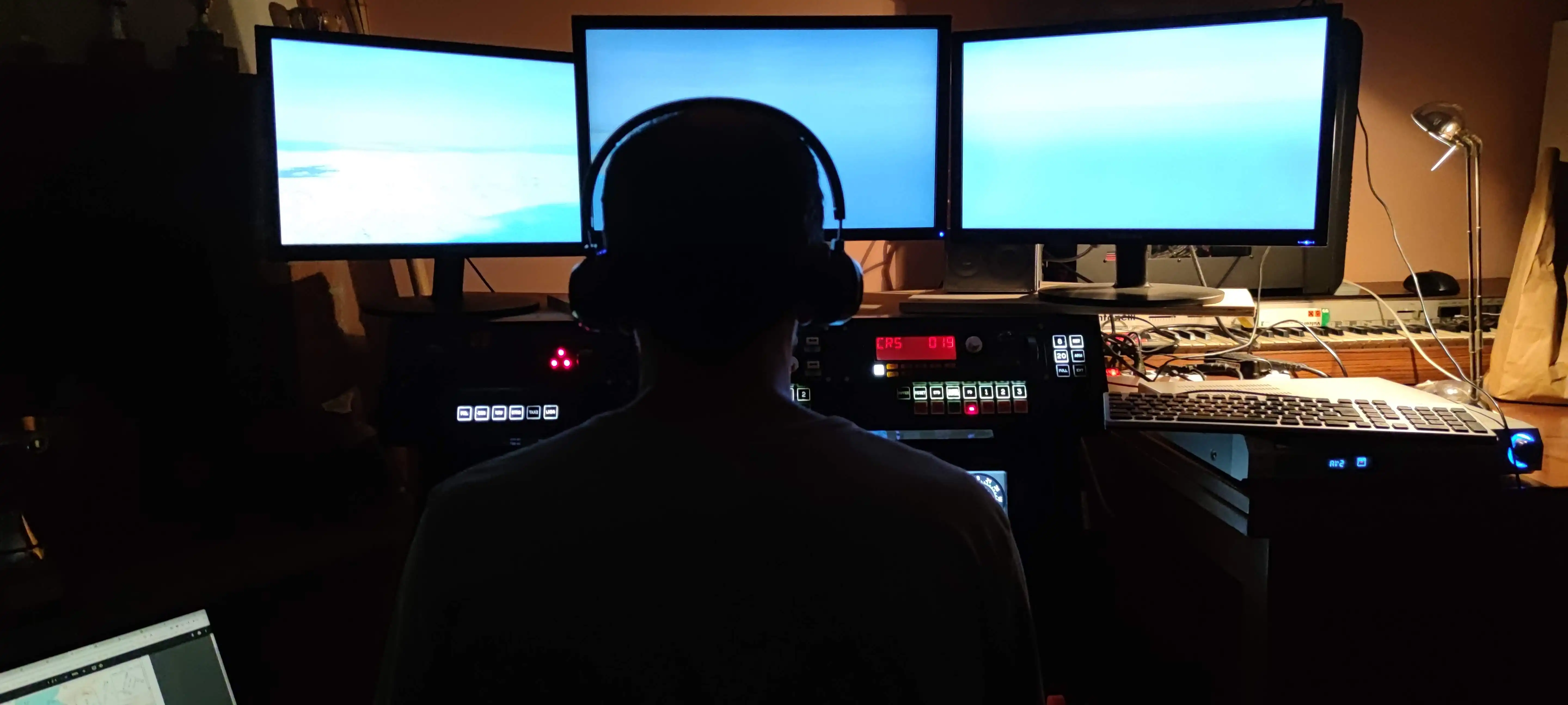
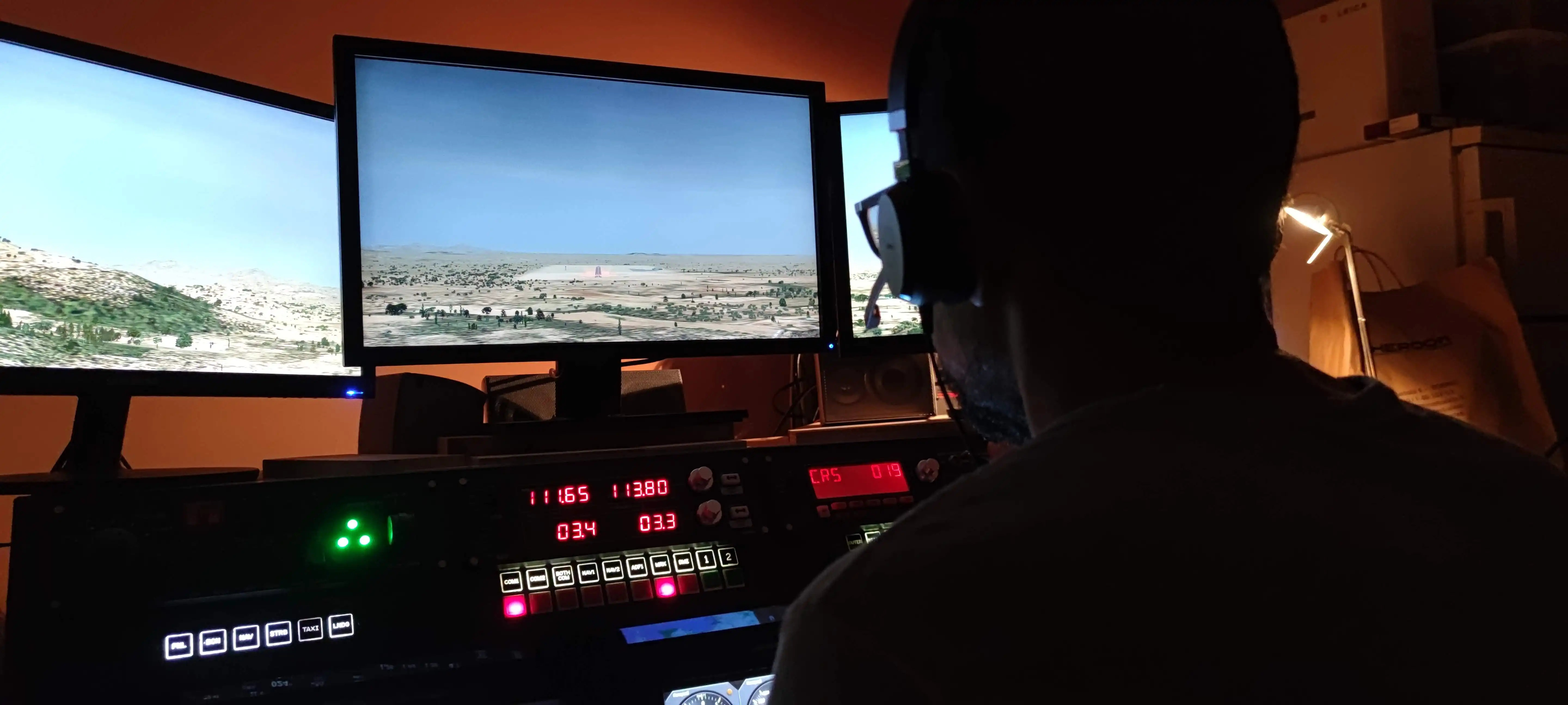
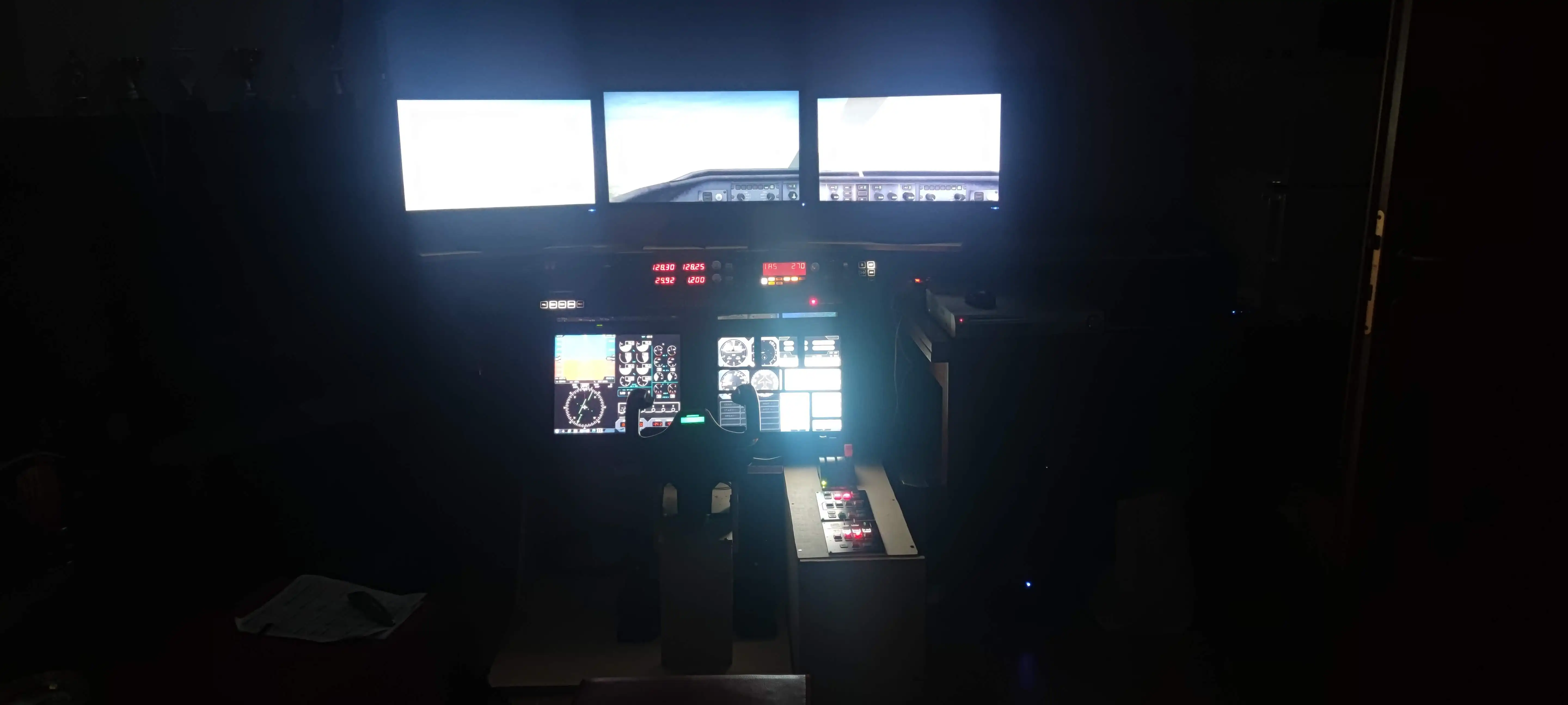
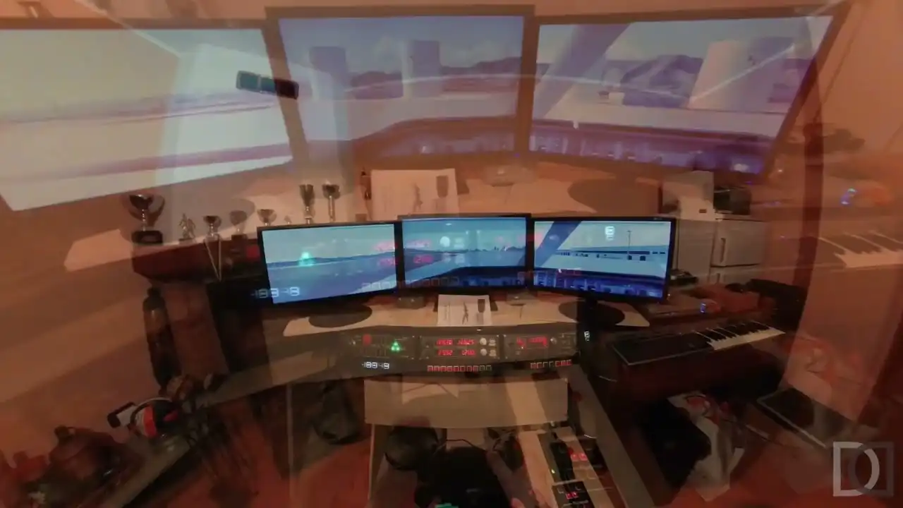
One of the most important parts of the simulator is certainly the vision of the "outside world", where our plane flies. I discovered with various tests that size is important, but above all depth is fundamental, the idea of being immersed in the virtual world.
In the early stages of my simulator, I had started designing the visual system using a Full HD projector. Image very large but too flat ... did not give the idea of being present in the world. So I abandoned this idea to switch to a multi-monitor system, which, to the detriment of size (I don't use big monitors at this moment), led to an important improvement in terms of depth.
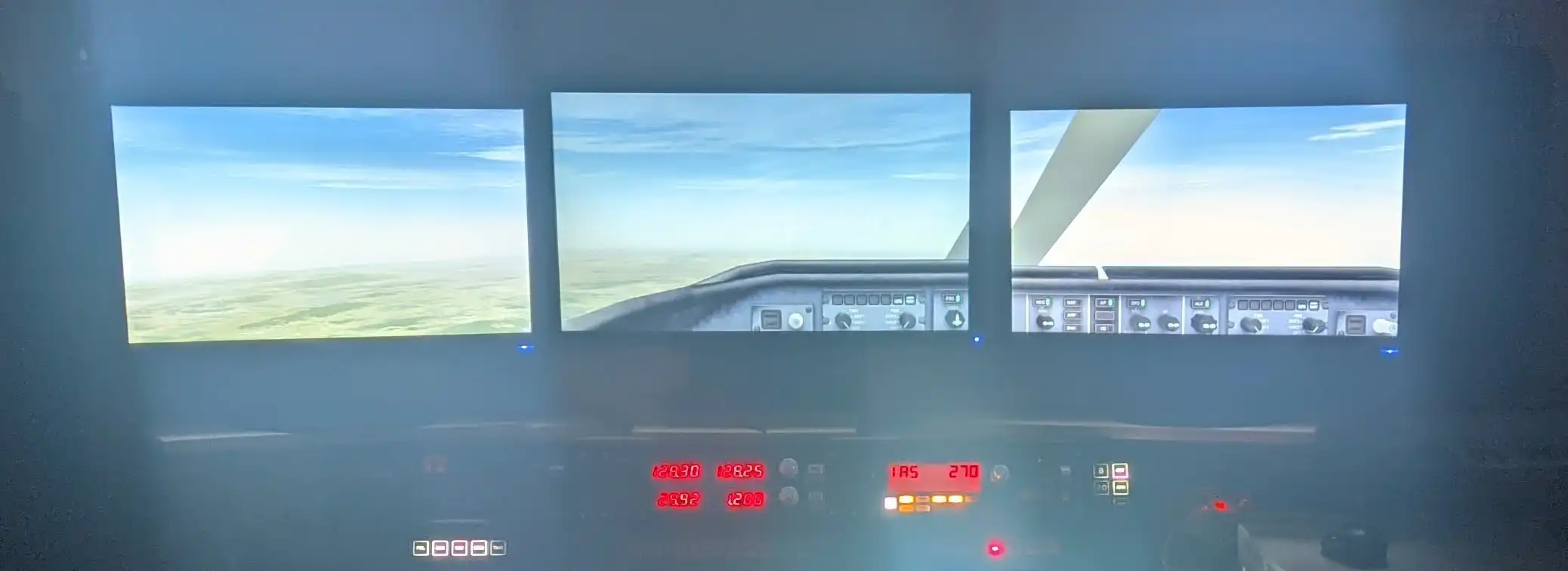
My current setup consists of 3 24' Full-HD monitors, which allow for a visual angle of about 135°. Technically, the three monitors are all connected to the FSX PC which, thanks to the presence of two graphics cards, allows them to be managed and combines the resolutions together to have a single large "display", given by the union of the 3 monitors
To obtain this result, always from a low-cost point of view, I don't use additional hardware (such as the Matrox Triplehead2go or similar...), but a free software that manages to combine the three video outputs into a single one. This amazing software is called SoftTH http://www.softth.net and sadly it is no longer in development. Thanks to it, FSX sees a single video card with a resolution of 5760 x 1080
I don't know if this will still be my definitive configuration in the future, but for now it does its job very well.
Take a look at my video with monitors at work
Enjoy your viewing

AIR MANAGER panels editing - Cold and Dark
After a few days of study and experiments, I finally managed to modify and create the AIR MANAGER panels for the glass cockpit of my Home Cockpit for flight simulator.
In particular, with a simple modification, I was able to manage the Cold & Dark the panels are sensitive to the state of the aircraft battery. If the battery is off, the panels are "cold & dark", i.e. off; if the battery is on, they turn on.
Enjoy your viewing
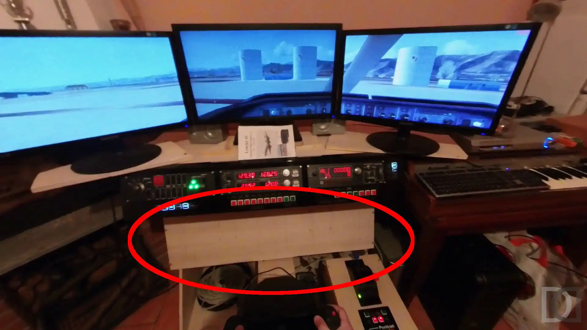
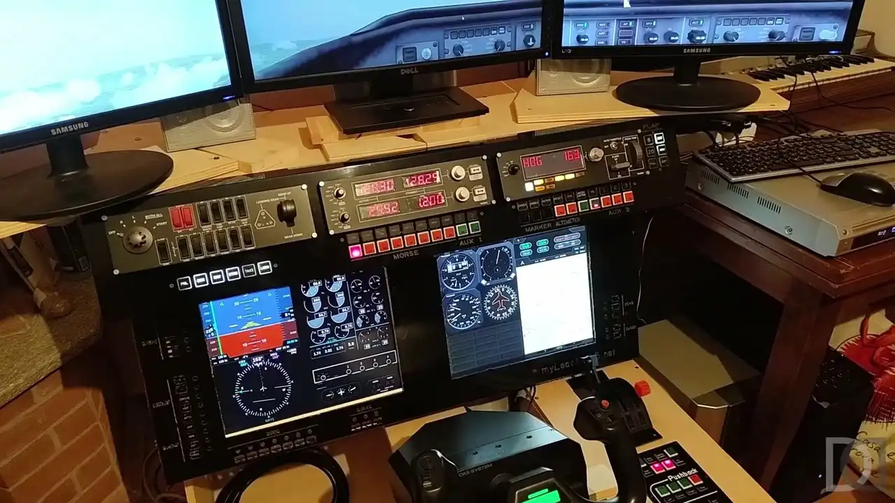
CUSTOM instrument panels
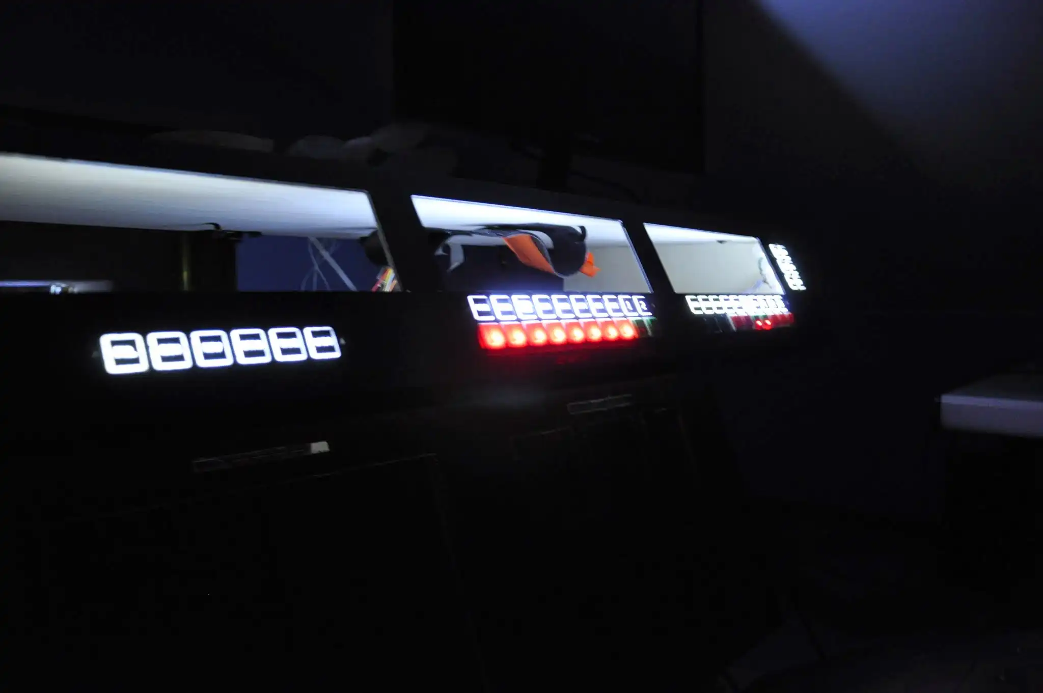
After talking about the commercial instrumentation, let's now see the homemade panels, which complete the basic simulator instruments.
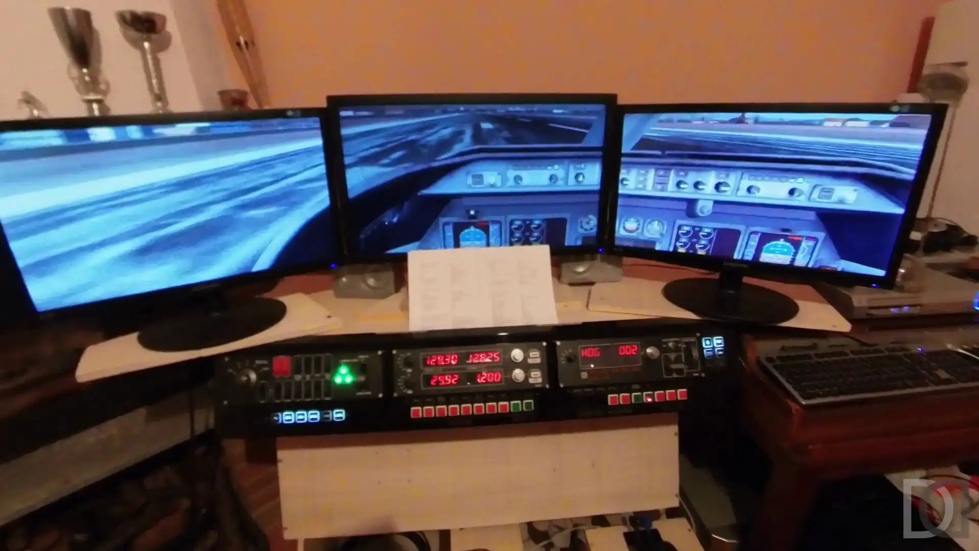
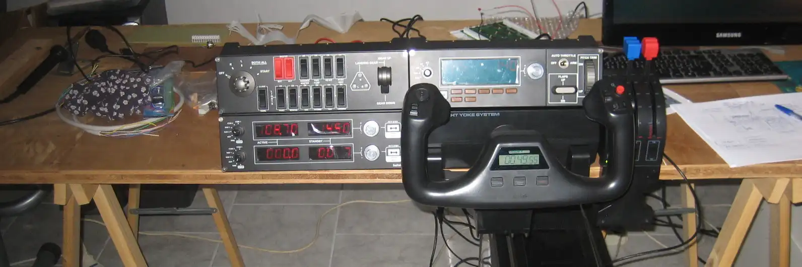
The first panel we are talking about is what I have called MAIN PANEL, i.e. the central part in front of the pilot, which develops horizontally.
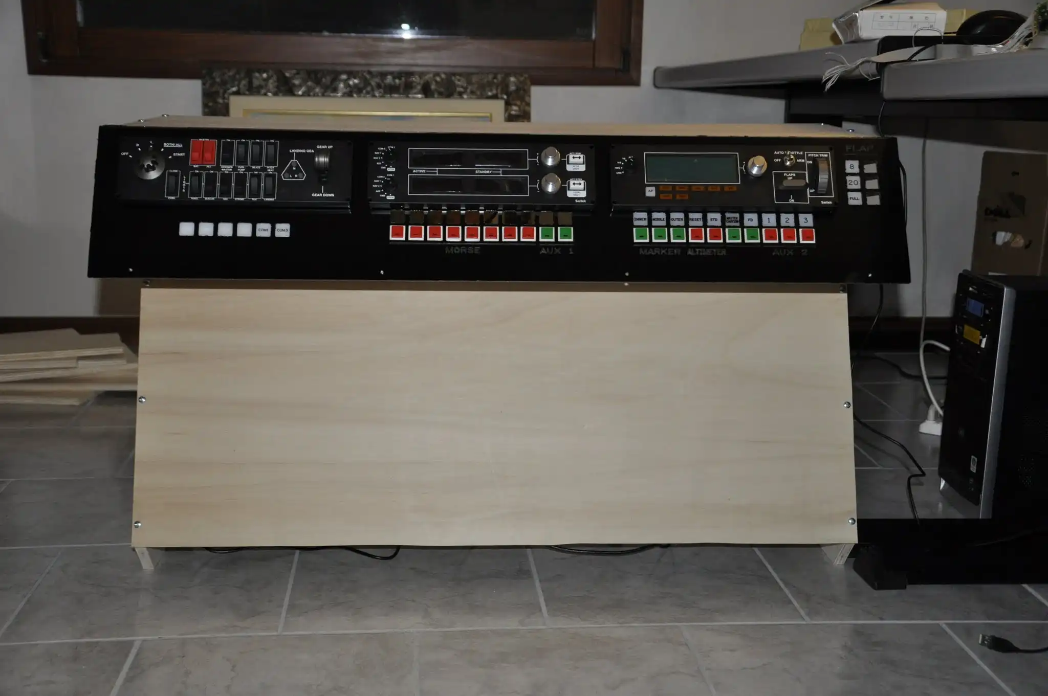
The MAIN PANEL in addition to the LOGITECH (ex SAITEK) panels, which we talked about in the previous post, contains rows of buttons and LEDs managed by software and electronic boards.
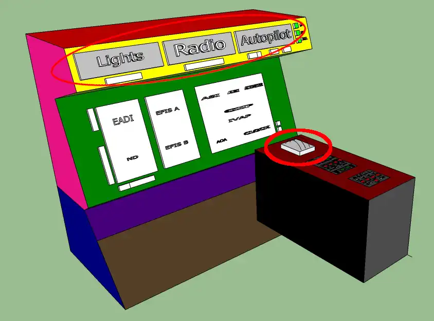
On the left we find the status indicators of the lights, which complete the flight switch panel located above which has the buttons to control the lights, but without the status LEDs.
In the central part, under the flight radio panel, we find the switches, with built-in LEDs, to manage the activation of the radios and the relative recognition morse code. Above the buttons, there is a row of LEDs which indicate the corresponding button.
On the right side, under the flight multi panel, we have some buttons with built-in LEDs for various functions, such as for example the marker indicators (inner, middle, outer), the management of the altimeter pressure setting, the master caution warning and the flight director.
On the far right we find the LEDs for the status of the flaps and the spoiler
The second home made panel is what I called CENTER PEDESTAL, i.e. a low panel positioned next to the pilot.
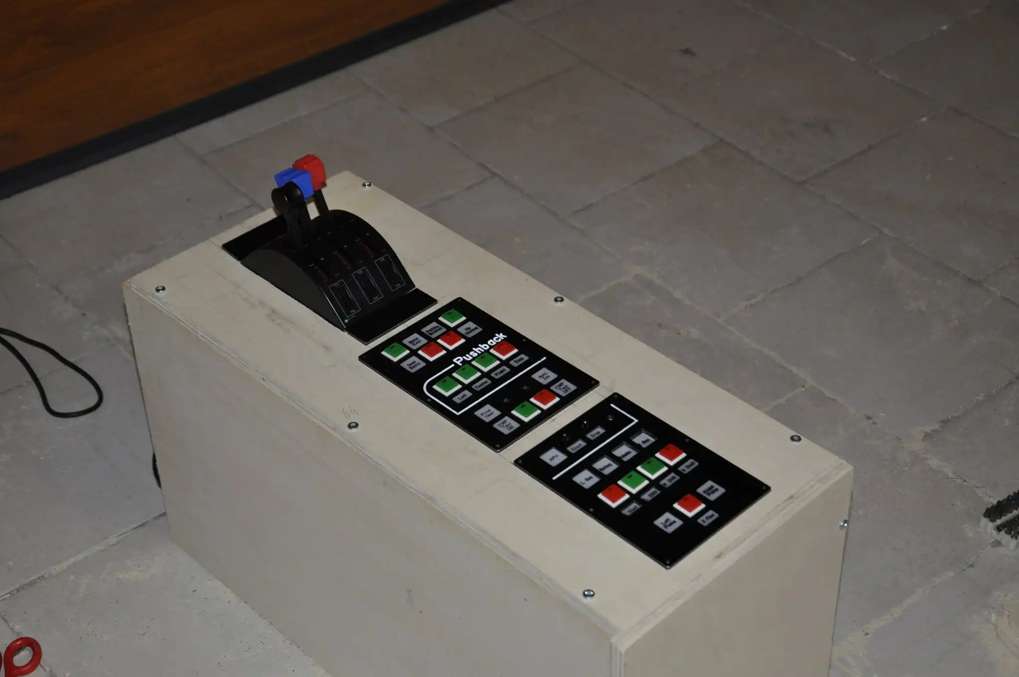
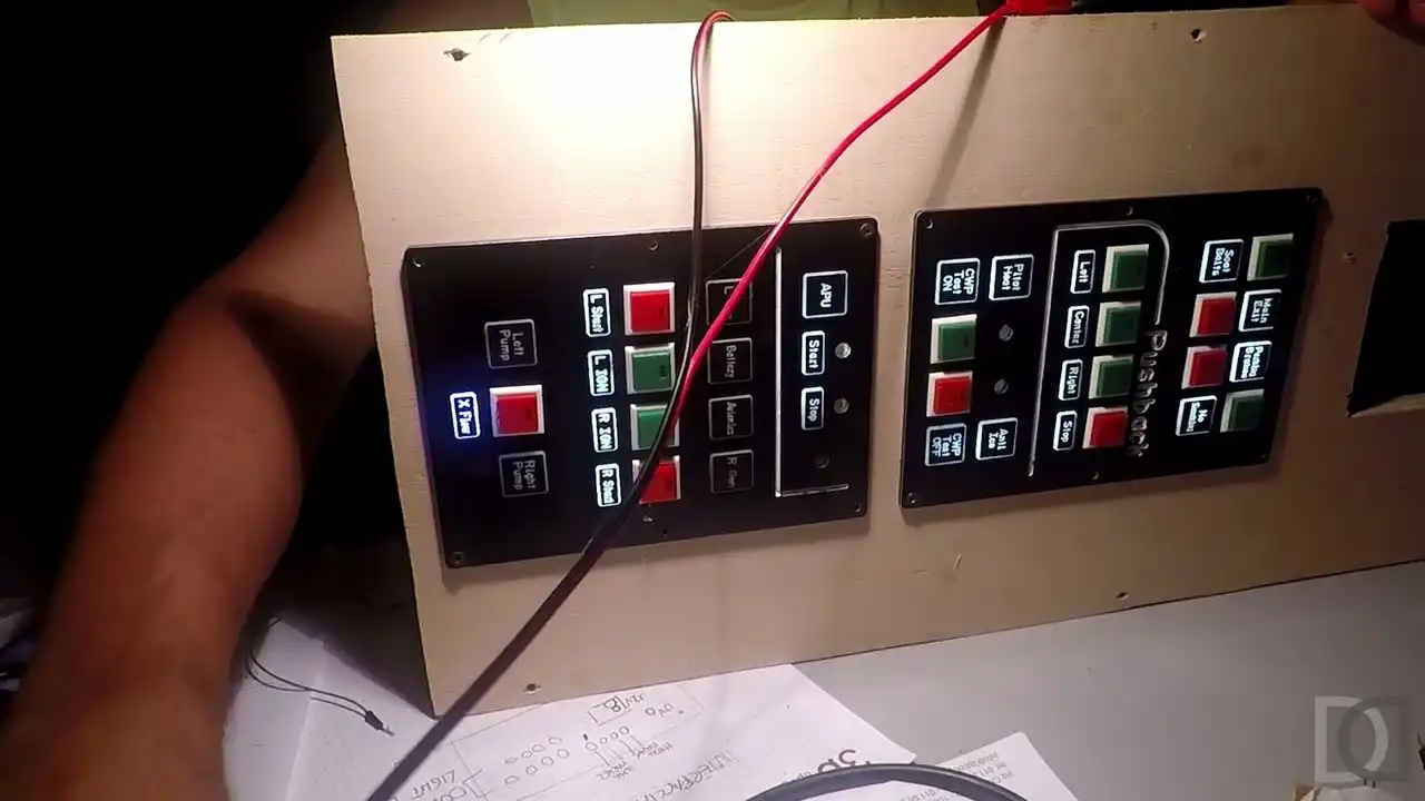
In this panel, in addition to the flight throttle system, with three levers for, respectively, the throttle, the fuel flow and the spoiler, which we talked about in the previous post, we find the GENERAL PANEL and the STARTUP PANEL, both made up of LEDs and buttons.
The GENERAL PANEL contains indicators and buttons relating to generic aircraft functions, such as pushback management, parking brake, door opening, etc etc
The STARTUP PANEL contains the functions for engine start management, such as the APU, fuel pumps, generators, etc etc
The buttons I used have the convenience of having the status LED incorporated, so they are both inputs and outputs
All buttons are connected to an Arduino Nano electronic board which interfaces with the simulator via the excellent MOBIFLIGHT software
The LEDs, on the other hand, are driven by an Opencockpits USBOutputs electronic board, which is capable, via the SIOC programming language, of activating the outputs (therefore turning on the LEDs) based on the status of the simulator.
But we will talk about this in the post dedicated to interfaces.
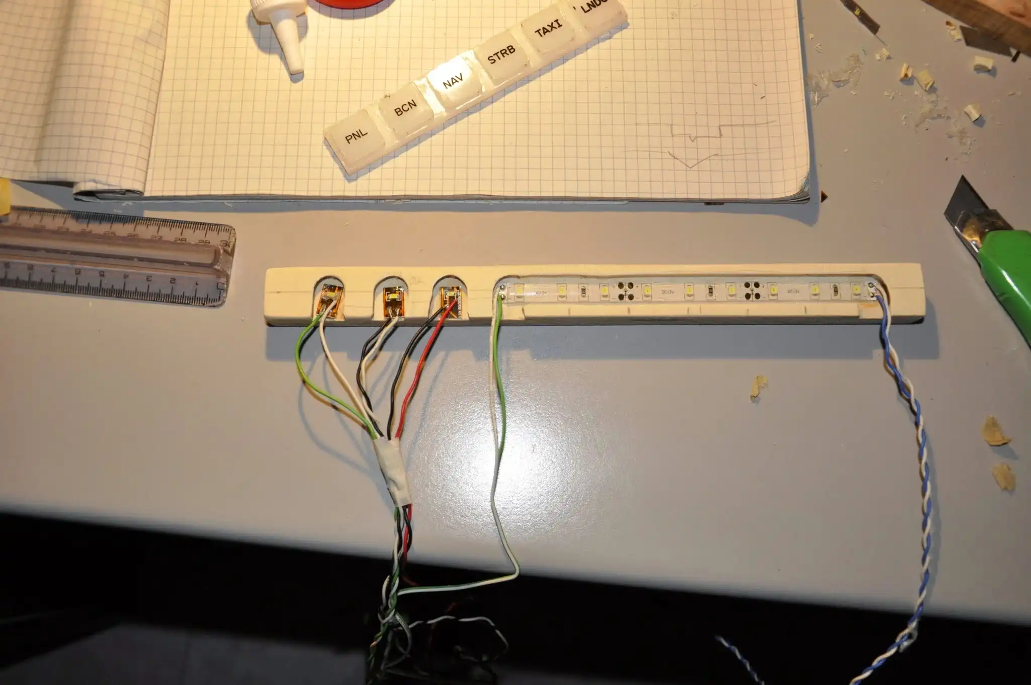
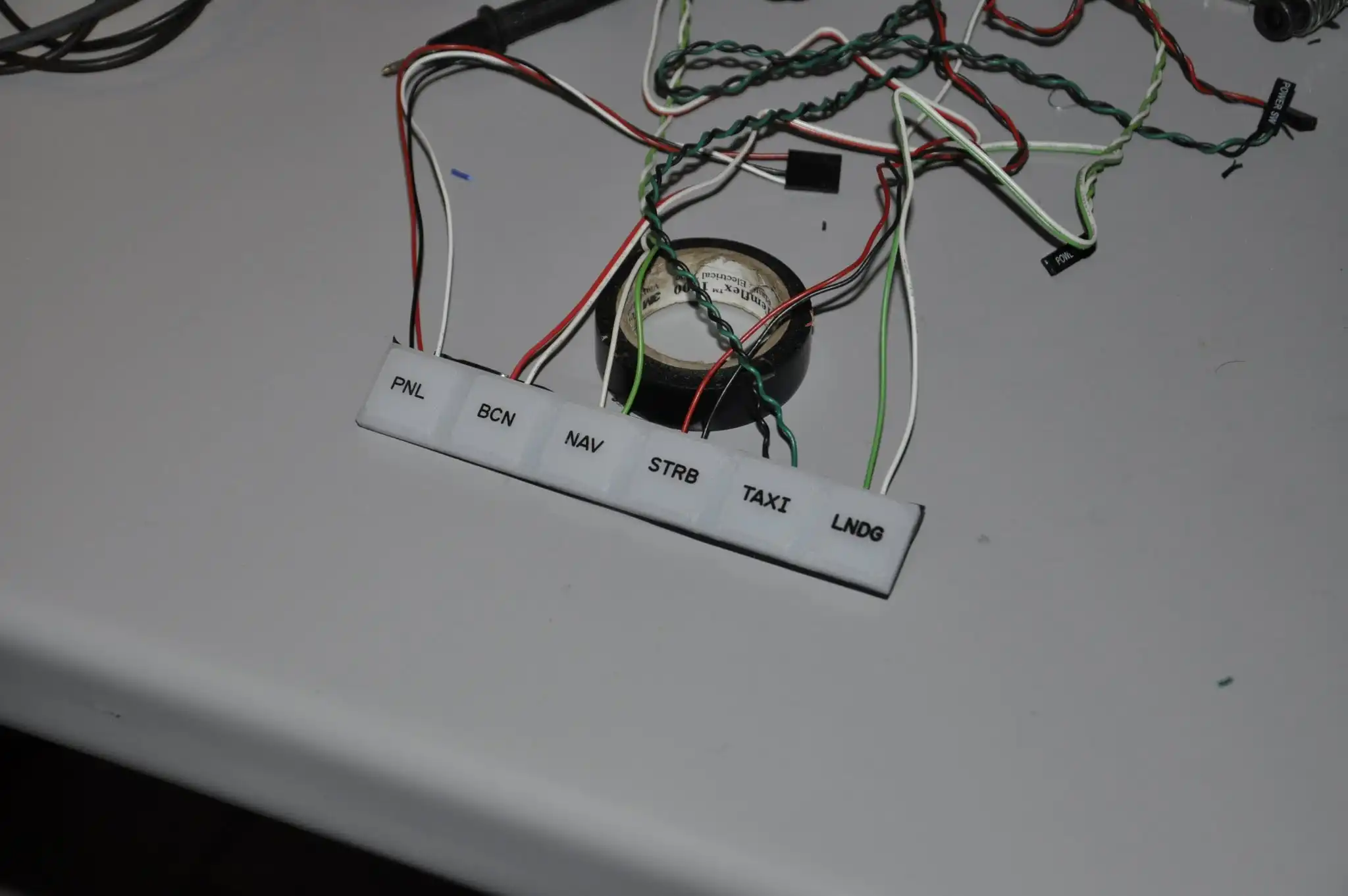
Single LEDs, on the other hand, are very simple pieces of LED strips glued to wooden guides that rest on a white plastic on which the labels to be displayed are printed. Also managed by the Opencockpits USBOutputs board.
LOGITECH (ex SAITEK) commercial instruments
Let's start with something simple: let's talk about the LOGITECH (ex SAITEK) panels and instruments that make up part of my simulator.
I currently own:
FLIGHT MULTI PANEL
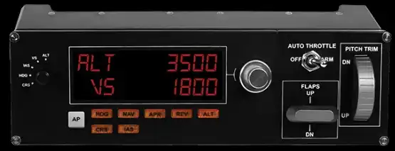
Used for complete management of autopilot, flaps and pitch trim
FLIGHT RADIO PANEL
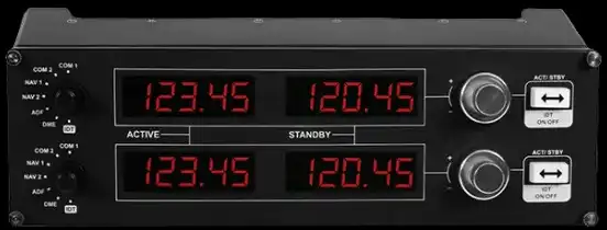
Used for the management of COM radio, NAV, ADF, DME and Transponder
FLIGHT SWITCH PANEL
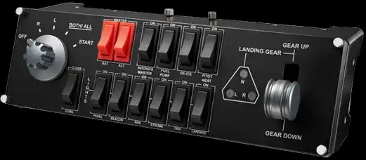
Used for electric management, engines, lights and landing gear management
FLIGHT YOKE SYSTEM
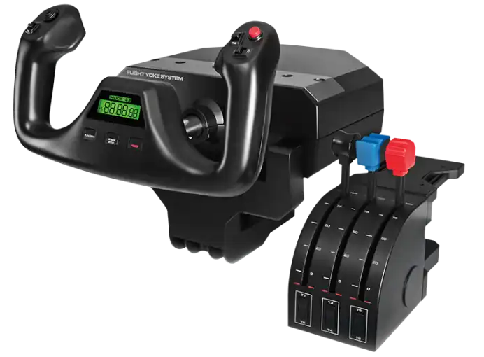
Steering wheel used as main control and the three throttle levers used for throttle, fuel flow and spoiler.
All aircraft control axes are handled by FSUIPC and not by the default Flight Simulator system, because FSUIPC allows me better control and calibration.
Also the three controls of the throttle levers (engine, fuel flow and spoiler) are managed, as analog axes, by FSUIPC. In particular, the throttle also manages the reverse, while the spoiler control allows, based on the lever position, to assign one of the three values managed by Flight Simulator (ARMED, EXTENDED, RETRACTED)
The buttons on the flyer have been combined with some simulator functions, such as view management and zoom; the bindings aren't final yet, because I'm trying various combinations.
At the moment I'm not using the buttons on the throttle quadrant yet.
FLIGHT RUDDER PEDALS
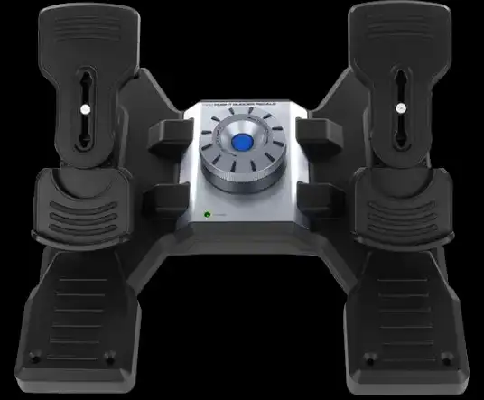
Used as rudder pedals and brakes. Also in this case the analog rudder and brake axes are managed and calibrated by FSUIPC.
They're all USB devices, so setup is relatively simple.
The three panels (Multi, Radio, Switch) are managed by a custom software called SPAD, which, at the time of my discovery, was free software (now it has become SPAD.next and is commercial https://www.spadnext.com)
This software allows you to configure and customize the various panels in an advanced way, in order to add new functions to them.
The three panels are placed into the main panel, upper part.
While the throttle levers in the center pedestal
Version 2 Simulator Structure

I think the time has come to update the information on how my Version 2 simulator is formed, always remembering that I am following a low cost philosophy.
Some things have changed from the previous version, even if the base has remained the same.
For example, I introduced the use of Mobiflight, an excellent open source system for managing buttons, eliminating the use of a keyboard interface card.
I changed software for managing the Glass Cockpit, using Air Manager (commercial software) to replace open source software that is a bit dated and not very customizable.
So, starting today, I will start a series of posts to describe the different hardware and software components, purchased and home-made, that make up the current version of my simulator, which is always in Work in progress.
So let's start with an introductory post, for a quick summary of the different components, waiting to get to specific posts in case more details are needed.
The system consists of two computers connected to the network, the main one for the Microsoft FSX Gold Edition simulator and the secondary one for the Glass Cockpit managed by Air Manager.
The visual part of the simulator is managed by 3 Full Hd 16:9 monitors connected to two graphics cards of the main computer, managed by the SoftTh software.
The glass cockpit is managed by two 4:3 monitors connected to the secondary pc.
Yoke, pedals and throttle are Logitech instruments, the same for the radio panel, the autopilot and various switches (lights, landing gear, battery...).
Everything else is managed by buttons that are interfaced to the simulator using an Arduino MEGA board on which the Mobiflight firmware is installed.
All the LEDs that are not managed by commercial components are interfaced to the simulator via the OpenCockpits USBOutputs board, programmed in SIOC language and compatible with FSUIPC.
Finally, the audio system is managed by a small 5+1 surround amplifier, to which I connected 3 speakers (2 front side + central) and the subwoofer.
In the next posts we will start by detailing the different components, seeing how they have been used in my current setup
Stay tuned...
Managing HOME COCKPIT buttons with MOBIFLIGHT and ARDUINO
Anyone who has followed the construction of my Home Cockpit in the past years knows that I used a standard keyboard circuit to interface the simulator buttons.
I talked about it (many years ago!) in this post /en/blog/learjet-45-home-cockpit/post/2012/02/handmade-input-interface.html
The idea was very interesting and really low cost...by disassembling a simple keyboard and putting a lot of patience in soldering all the contacts it was possible to create an input interface to be able to manage all the buttons in a very simple and low-cost way.
Unfortunately a few months ago, during the recovery phases of my Home Cockpit, due to some wrong connection, I managed to burn two keyboards.
So I started thinking about some other alternatives (also because I had run out of keyboards!) and I came across the fantastic MOBIFLIGHT.

In few words, MOBIFLIGHT by Sebastian Möbius is an Open Source project that allows the integration of standard hardware with your flight simulator.
Using for example the famous ARDUINO microcontroller, it is possible to manage INPUT (buttons, potentiometers, ...) and OUTPUT (led, lcd, servos, ...) of the simulator.
There is an excellent Wiki on the official GitHub page that allows you to learn more about the potential of this project: https://github.com/MobiFlight/MobiFlight-Connector/wiki
he official Youtube channel of the project is also a great source of information and support: https://www.youtube.com/@MobiFlight
After reading the documentation and watching some tutorials on Youtube, I decided that MOBIFLIGHT could be for me.
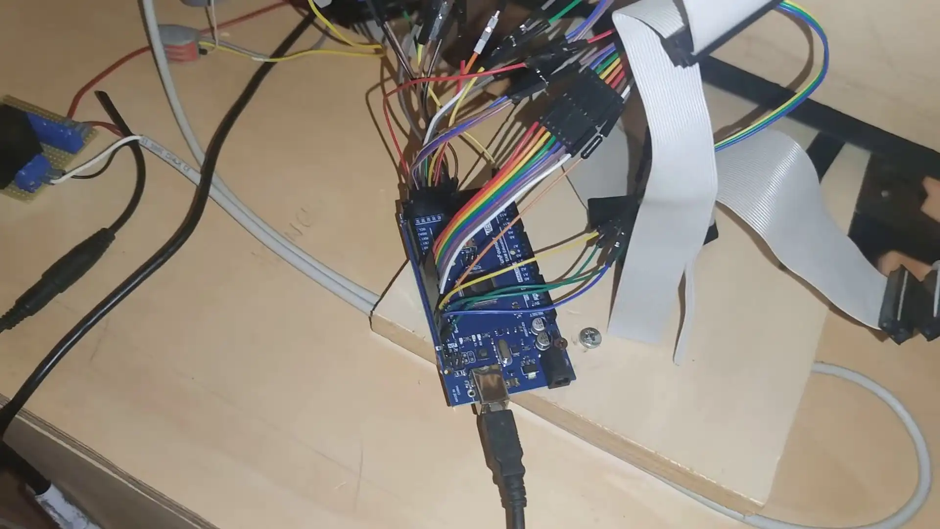
Fortunately at home I had some unused ARDUINO UNO boards (thanks to my home automation experiments) and so I decided to give it a try, even if that particular type of board (ARDUINO UNO) is not in the list of officially supported ones (https://www.mobiflight.com/en/documentation/module.html).
So I create a very simple test case: a button connected to the ARDUINO UNO pins which triggers a "virtual" event towards MOBIFLIGHT.
So let's start with the download and installation of MOBIFLIGHT CONNECTOR, a software for Windows that allows connection with the simulator and complete configuration management.
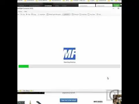
When first started, MOBIFLIGHT CONNECTOR scans the system for connected ARDUINO boards. In my case, even if not officially supported, my ARDUINO UNO is immediately found; I'm also prompted to install the MOBIFLIGHT firmware inside, which I do immediately.
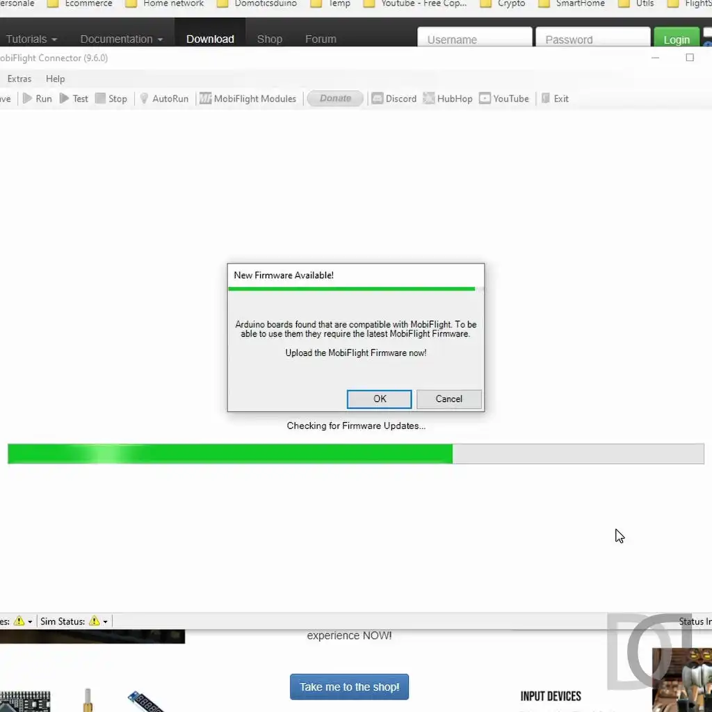
The firmware is a particular software that is installed on microcontrollers to instruct them on how to manage INPUT and OUTPUT connected to them.
In this case, the MOBIFLIGHT firmware is part of the project and is necessary to allow the ARDUINO board to understand how it has to manage the various devices connected to it. This operation is done only the first time a new ARDUINOboard is used. If firmware updates are published, the system will ask us whether or not we want to perform the update.
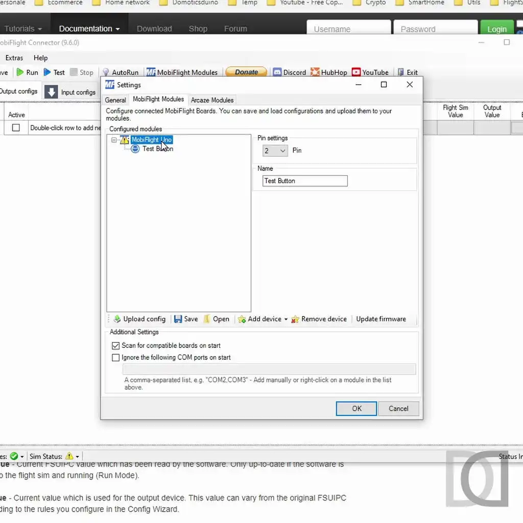
With the firmware installed, ARDUINO is immediately recognized as a MOBIFLIGHT Module to be configured.
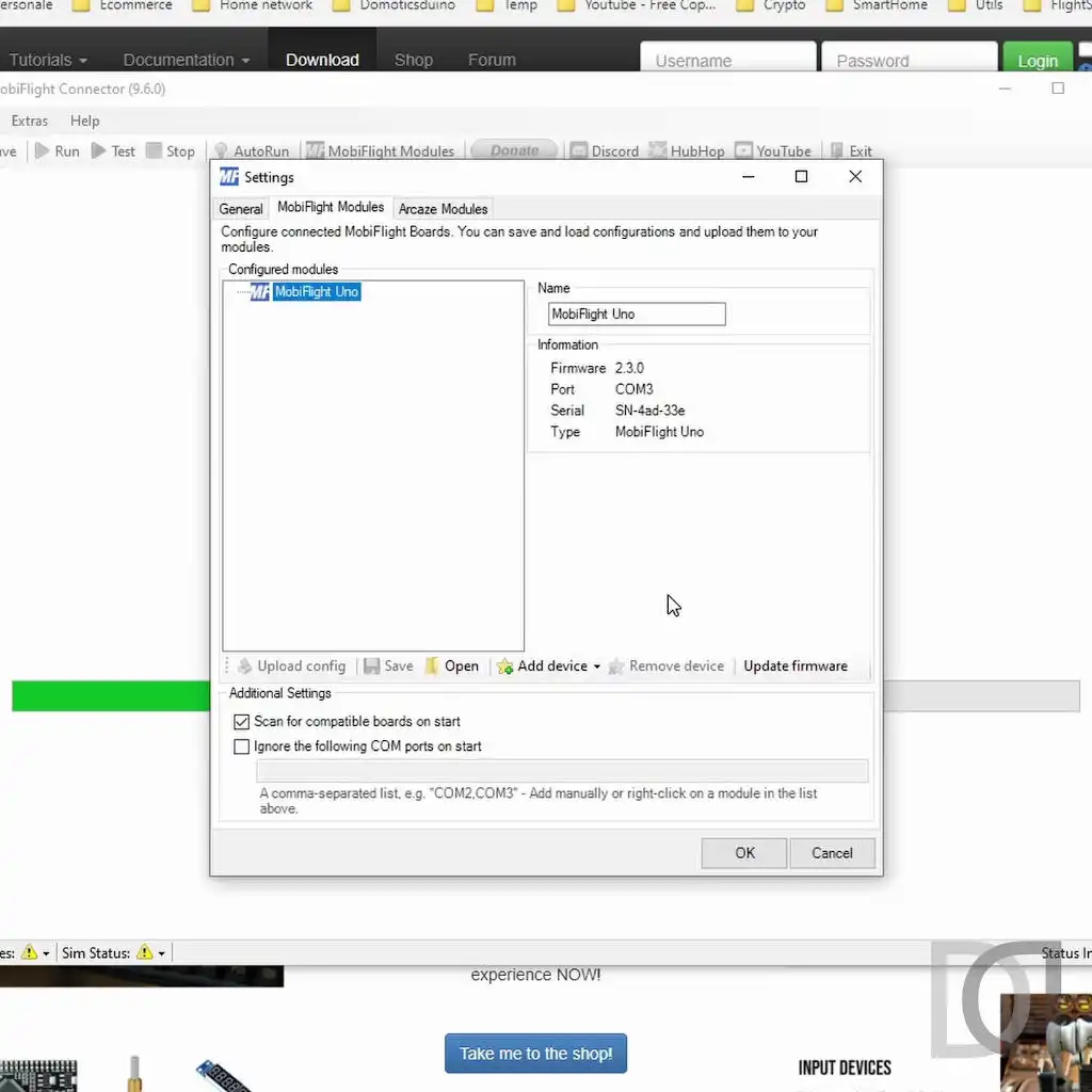
We are therefore ready for the actual configuration
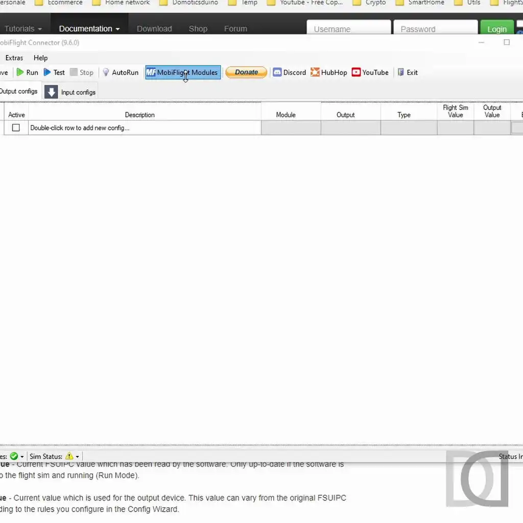
At this point, we connect our test button to an ARDUINO INPUT PIN and add it in the module configuration on MOBIFLIGHT, taking care to insert the correct pin number.
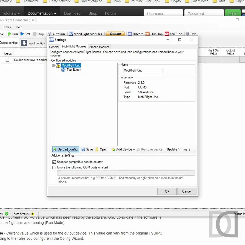
Every time you make a change to the module configuration, you must remember to update the configuration on the board, using the Upload config function.
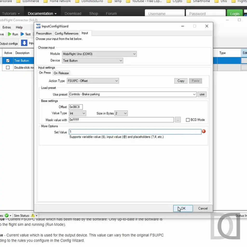
We then move on to the INPUT configuration to assign a function on the simulator to the test button created previously.
In my case, I assigned the parking brake, using FSUIPC offsets (I still use FSX).
At this point we are ready to verify the operation using the TEST function, which MOBIFLIGHT makes available to us, without the need to necessarily have the simulator turned on.
Below you will find a short video showing all the steps taken: from the first run of MOBIFLIGHT, to its configuration up to the final test, which took place successfully. The next step will be to buy an officially supported board (I'll get a compatible ARDUINO NANO), also because I need many pins to manage all the buttons and with ARDUINO UNO I wouldn't have enough.


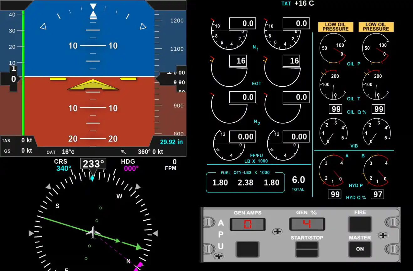
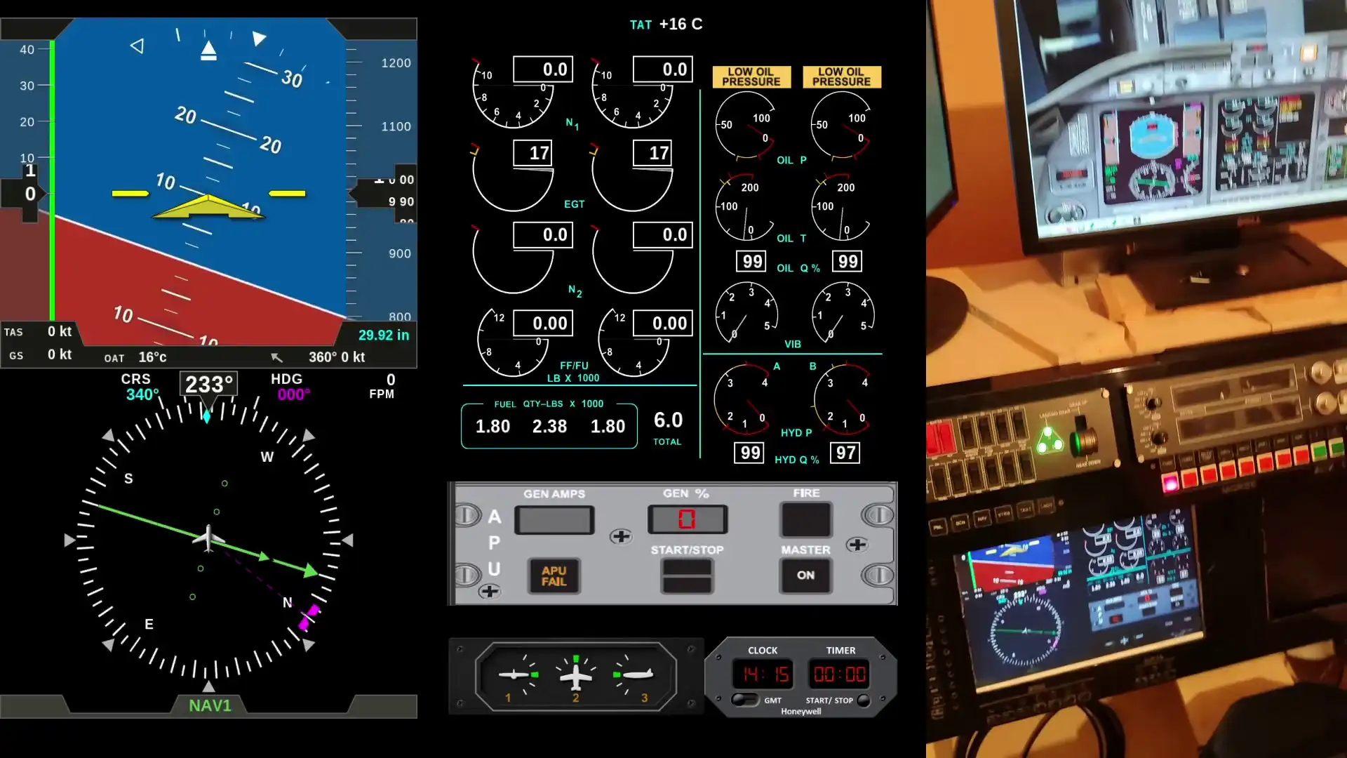
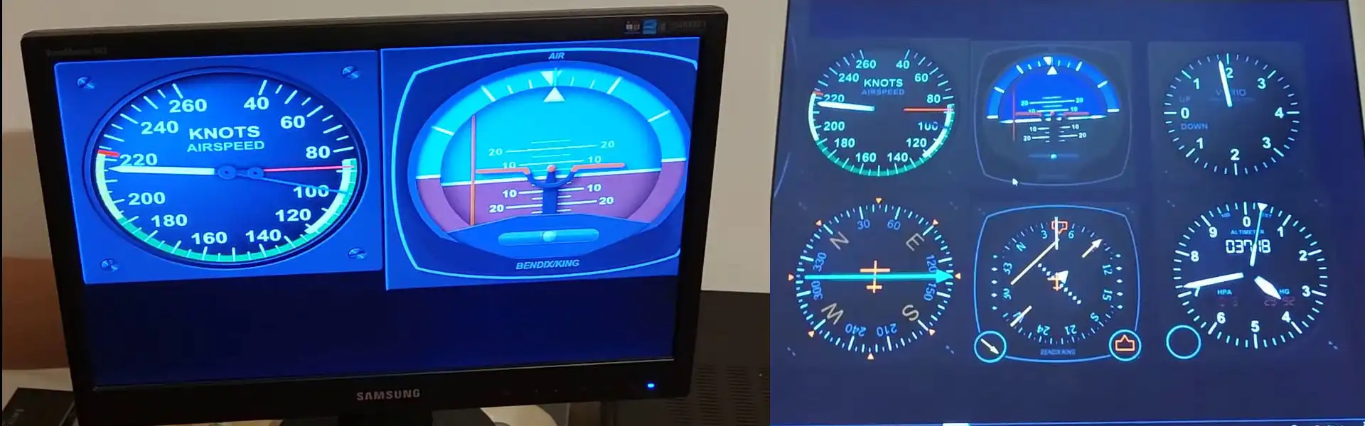
GLASS COCKPIT with AIR MANAGER
After successfully testing the free version of AIR MANAGER, I decided to buy the commercial version to have access to all the features and be able to download a whole series of panels and community-developed tools.
Before I can actually use it, I have to do one last preparation step: reassemble the GLASS COCKPIT monitors on the front panel.
The monitors are connected to a surrounding PC running only AIR MANAGER and connected by network to the FSX PC
This is the area where the monitors should be remounted
These are the monitors
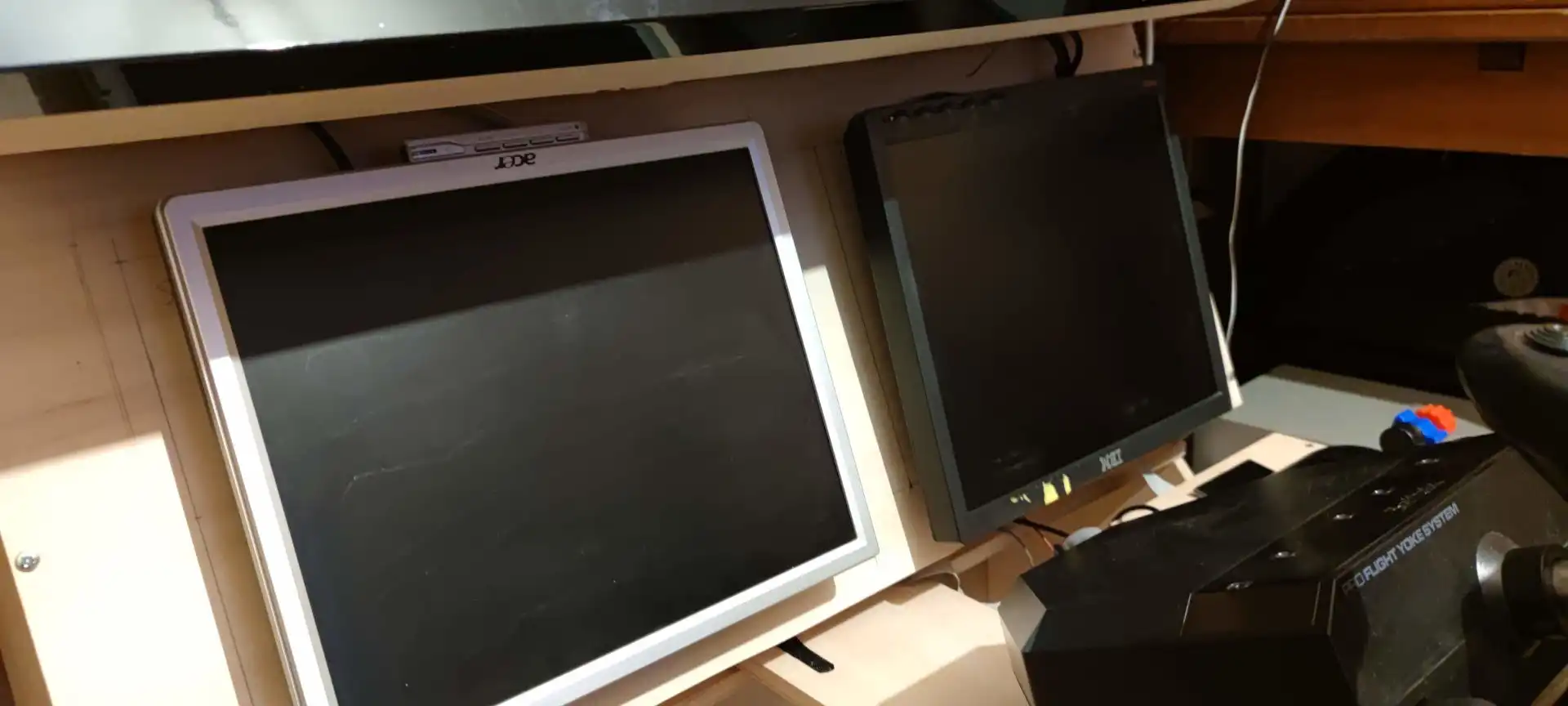
And here is the final result, with a plastic cover over the monitors and AIR MANAGER running
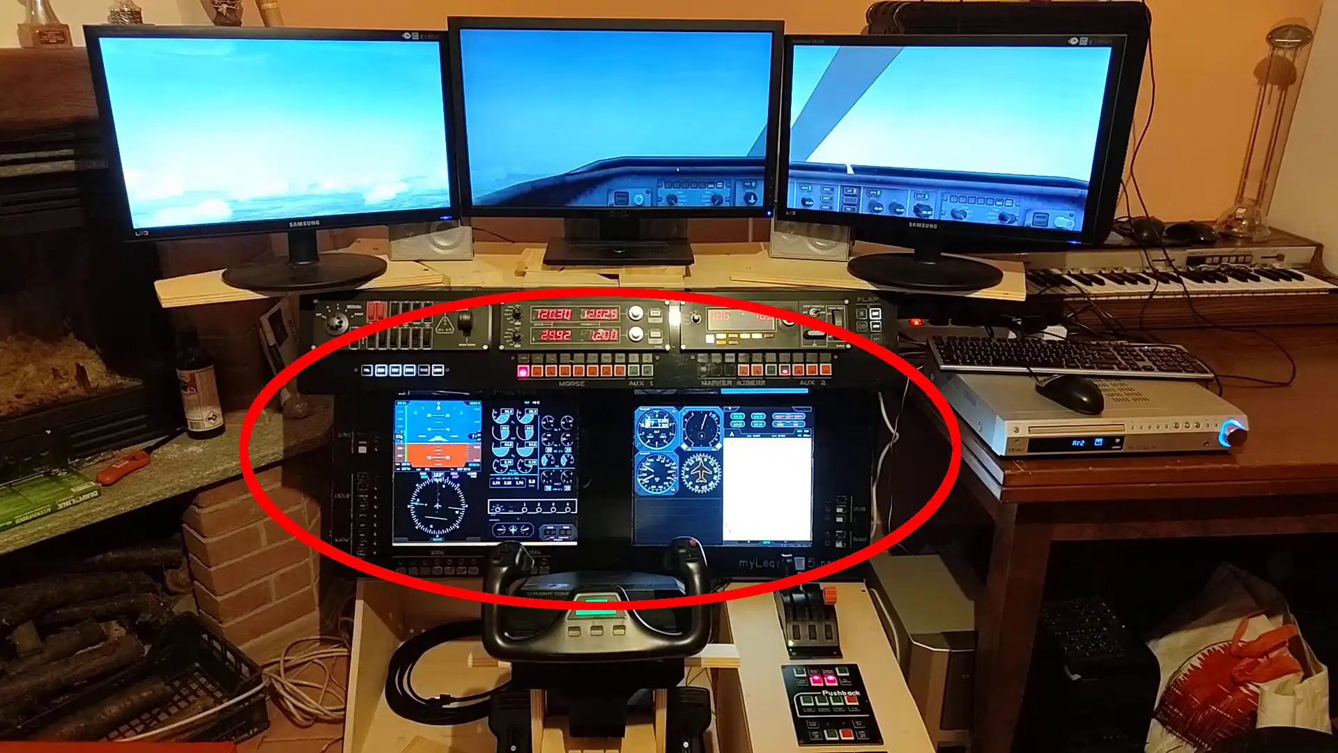
At this moment I'm using just free panels, downloaded from the siminnovations website. This is the link: https://siminnovations.com/community-panels
My idea is to try to develop some panel / instrument, starting from one of those already available.
Here you can find a short video about my actual Glass Cockpit
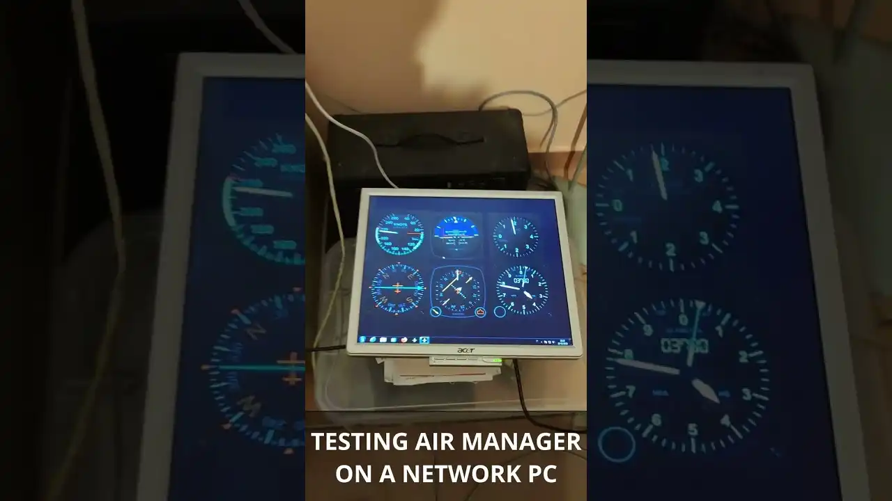
Testing AIR MANAGER with a network PC
The time has come to resume the Glass Cockpit, still missing in the current version of simulator
In Version 1 I had implemented it with some software that I had found on the net but which, unfortunately, were not very flexible and above all were not very optimized and often crashed the PC that managed them.
Here you will find two posts where I talk about it /en/blog/learjet-45-home-cockpit/post/2013/05/glass-cockpit-assembly.html /en/blog/learjet-45-home-cockpit/post/2013/11/glass-cockpit.html
However, I thank Dave Ault for having created them and made them available...without him I might not have discovered the possibility of creating a glass cockpit.
I've certainly arrived late, but I've recently discovered a great software, AIR MANAGER, to create panels for the different flight simulators (FSX, P3D, X-Plane and of course FS2020).
It is not free software and is sold by Sim Innovations .
The price is not affordable and the potential is very high.
I'm not here to speak about its characteristics, also because there is a lot of material on the net, but in a nutshell I tell you that it allows the creation of any type of panel and instrument which can be interfaced with the main flight simulators.
To develop a panel or tool from scratch, you need to have some programming skills, read the API docs it and learn the LUA scripting language.
For those who don't want to be involved in programming skills, the community provides a whole series of already implemented panels and tools to choose from.
It is also possible to start from one of them and make changes to make it more useful for your goal...I will probably adopt this strategy, mainly for a matter of time.
That said, before buying it, I downloaded the free version that allows you to try it with just one panel. I wanted to make sure it could work on my old Glass Cockpit PC which is still running Windows 7 (and I'm not planning to upgrade it right now).
In the following video the result, extremely positive.
The next step will be to purchase the full version and start playing with the various panels, reassembling the monitors in their place in the simulator.
POV - Startup, Taxi and Takeoff
In this video I check the engine startup, taxi and take-off procedures from Turin Caselle LIMF runway 36, using Microsoft FSX
The simulator is not yet complete; all the Glass Cockpit instrumentation is still missing
Enjoy your viewing
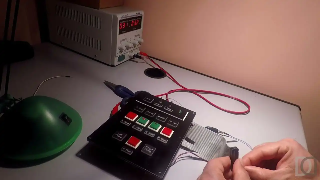
Assembled Startup Panel Led
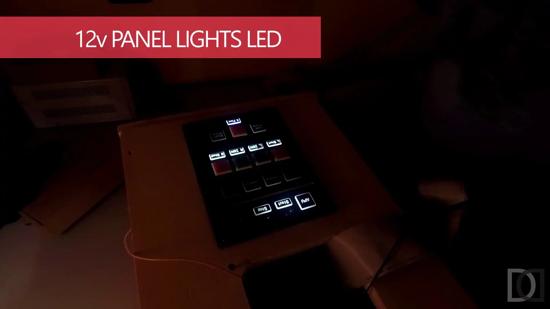
Test of all the led of the assembled startup panel. There are two types of LEDs
- 12v for the panel lights, always on or always off
- 3.3v for the status lights, switched on or off according to the state of the simulator
Enjoy your viewing
Center Pedestal Lights
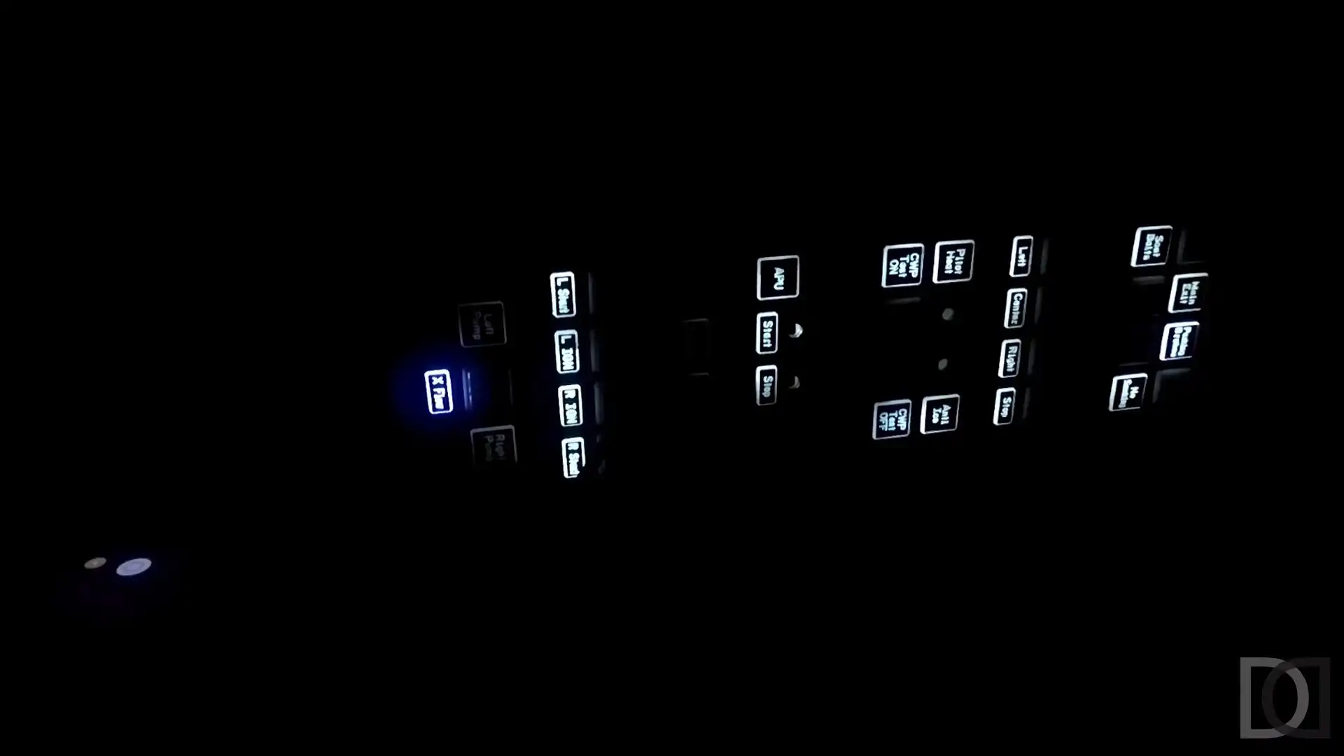
Arrangement of the fixed LEDs of the center pedestal, using wooden cuts to be embedded in the panels.
Enjoy your viewing
Let's start again with Version 2
New restart for the "version 2" of my Home Cockpit, let's hope it's the right time.
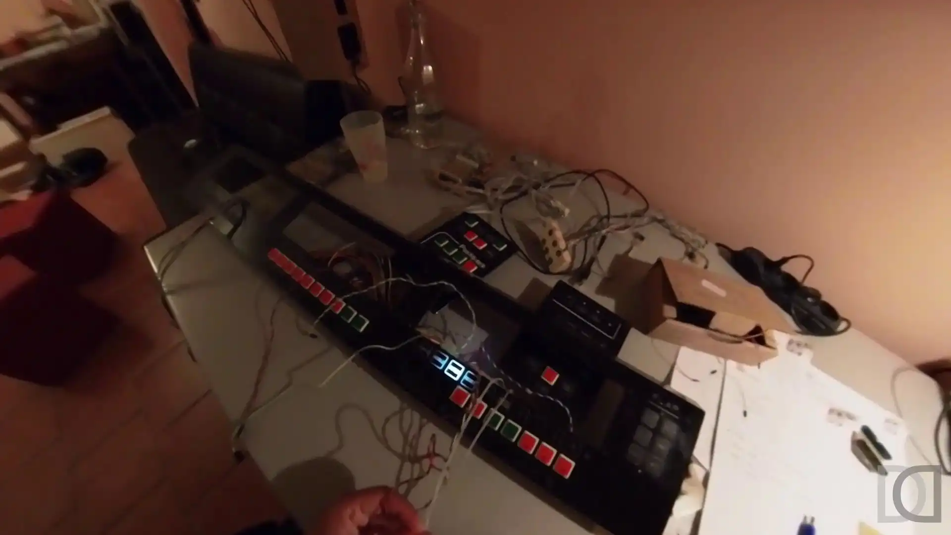
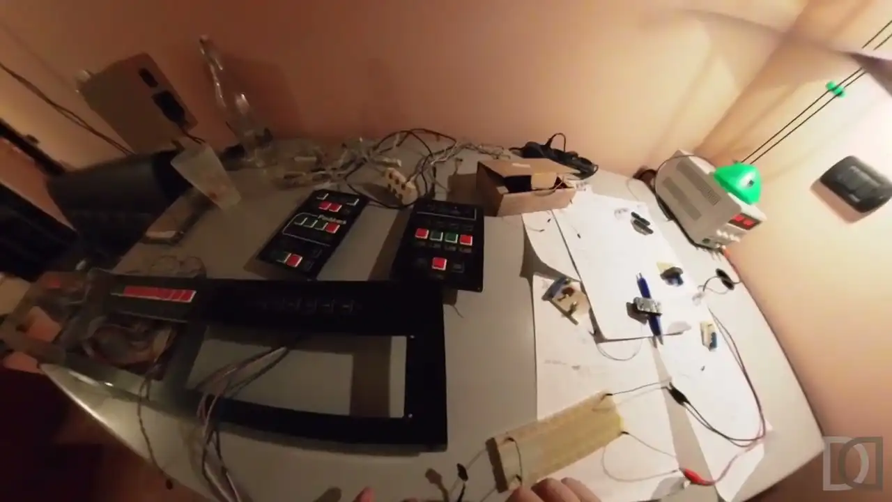
After having disassembled everything, let's start by checking the LEDs of the various panels.
Enjoy your viewing
Flying with Falchi di Daffi
 |
| Cellarengo, the town |
 |
| Cellarengo, S. Firmino, our houses... Alessia and Luisa looking for us (see red circles) |
Here is a video about a real flight on Sunday 27/12/2015, with Falchi di Daffi on the Sierra Whisky plane, a CESSNA C172 REIMS ROCKET. We flew over Turin, Moncalieri, Poirino, Cellarengo (see photos above), Valfenera and landed at Castelnuovo don Bosco.