My Learjet 45 Home Cockpit (63 posts)
22/02/2013
First Wiring - MORSE CODE Panel
by Marco
After a long stop, due to a busy period at work, I made some tests about wiring up buttons and leds.
I started on first block on main front panel. In particular, the MORSE CODE panel, made up of 8 buttons + 2 aux (not used yet) and as many leds.
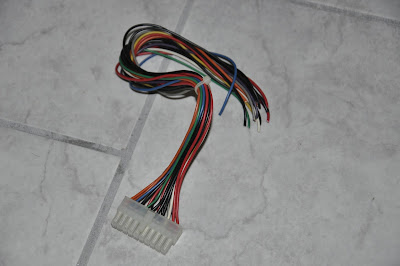
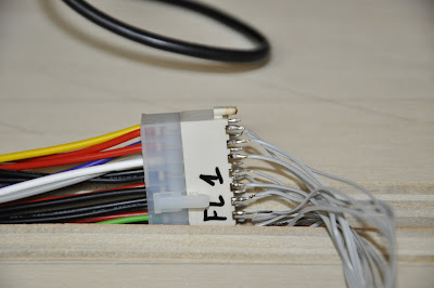
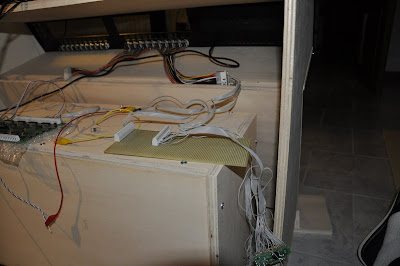
My wirings are completely "handmade", made by some PC recovered components. To wire up the buttons and their integrated LEDs I used ATX connectors, taken out from an old power supply.
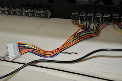
The female connector was unsoldered from a main board of an old PC (thanks to the help of Piero's Phon); using a flat cable (the one used to link Hard Disk to IDE interface) I brought signals related to buttons on a breadboard (which is interfaced to the usb keyboard) and signals related to leds directly into the Opencockpits UsbOutput card.
Do you think they will be enough???
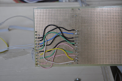
- Flat cable soldered to ATX pins
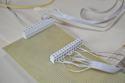
- The breadboard used to link buttons and usb keyboard
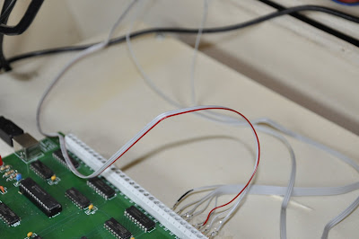
- Flat cable termination linked to Opencockpits Card outputs
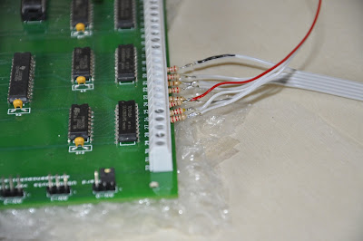
- Particular of Opencockpits Card output, with the linked resistors
The breadboard is used to link buttons and usb keyboard pins; this target is achieved mapping the relative signals:
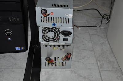
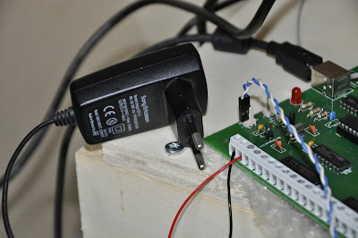
At last, I used a 5V power supply for the Opencockpits Card, in order to get the adequate power to manage all leds (I don't think USB power would have been enough :) )
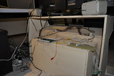
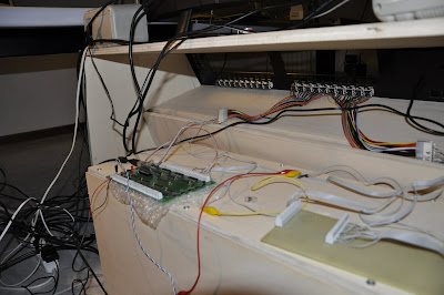
Some general shots:
and a video: